A four-member team at Structural Dynamics Research Corporation (SDRC) has completed the preliminary design for a new spinning ride for Disneyland.
The team includes one graduate student and three undergraduate students in Engineering Mechanics and Astronautics, whose experience in advanced and structural dynamics will contribute to the creation of a world-class ride. Additional skills that the team will bring to the table include extensive programming experience in Matlab and Mathematica, as well as finite element modeling in Ansys.
The ride features two non-collinear components of angular velocity, and the head of each of
the two passengers will experience a maximum of  of acceleration. The ride is specifically
designed to be light, safe, affordable, and fun.
of acceleration. The ride is specifically
designed to be light, safe, affordable, and fun.
The team at SDRC would like to perform a more detailed design and analysis of the ride, so the following pages provide contractors at Disneyland with an overview of what they can expect from the ride. Safety considerations and acceleration calculations are highlighted, and some information on team members and a project management plan are also included.
The next step after this initial proposal will be a detailed structural and failure analysis on the system, which Disneyland can expect in December.
The Flight Simulator will be equipped with multiple safety measures to ensure that the pilots
have a fun and exciting ride. In order to ride the Flight Simulator, each passenger must be at
least  feet tall. This insures that the riders can be securely fastened into the seat. Assuming
an average rider weight of
feet tall. This insures that the riders can be securely fastened into the seat. Assuming
an average rider weight of  pounds, one single rider cannot weigh more than
  pounds.
Any more weight will induce a moment on the main arm that might be considered unsafe. A
factor of safety will be factored into the building of the arm in case two riders combined weight
to be more than  pounds.
This is because with the extended arm and accelerations the main arm will be subject to, it is believed to be the first membrane to fail. In order to start the ride, it must be certain that the arm will not break during the ride. While riding, each rider will be harnessed into his or her seat via a 3-point harness.
The harness will let the passengers fly upside-down while still secured in the cockpit. Since
the Flight Simulator will be subject to  acceleration, complementary sick bags will be
provided upon starting.
acceleration, complementary sick bags will be
provided upon starting.
In case of a medical emergency of a passenger or if it has been determined that it is unsafe to ride mid-flight, an emergency stop will be activated which will bring the ride to an end. When activated, the ride will right itself upwards while bringing itself to a stop about the center of the ride. This is so when the ride stops, the passengers are not hanging upside down which would be unsafe.
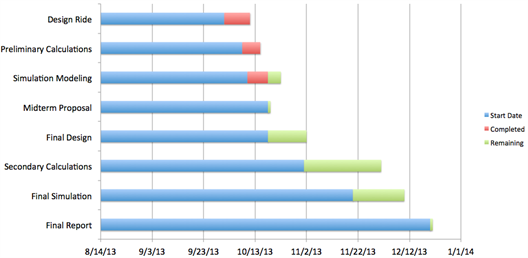
The following table describes the activities shown on the Gnatt chart above.
| Activity | Description |
| Design ride | Coming up with a ride that would be functional and meets all expectations. |
| Preliminary calculations | With ride chosen, calculations showing the velocity and acceleration of the rider's head symbolically. |
| Simulation modeling | Modeling the ride with a simulator with sliders to estimate the angular velocities. |
| Midterm proposal | When the midterm proposal of the ride is requested by the company. |
| Final design | Finalizing how the ride will work. |
| Secondary calculations | After finalizing how ride will work, will compute secondary calculations to know which velocities will work to add up to give the desired acceleration for each passenger. |
| Final modeling | Once the angular velocities are known, make a model to show how the ride will work when everything comes together. |
| Final report | When the customer wants the final report to know if they would like to purchase the ride that we have created. |
The velocity and acceleration of the ride object was derived such that it is valid for all time.
The derivered equations are used in a simulation program written for this proposal in order to
generate the acceleration time history and be able to modify the ride parameters more easily to
find the optimal combination to meet the given specifications of maximum  customer
requirments.
customer
requirments.
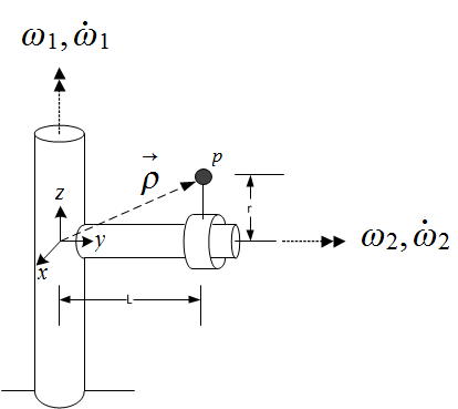
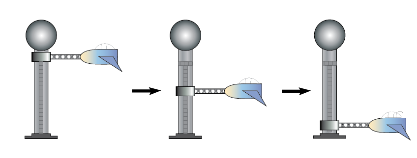
The simulation was done assuming the ride is at steady state, hence angular accelerations are set to zero. The following diagram illustrates the four design parameters used in the simulation and the expressions found for the velocity and acceleration. The appendix contains the detailed derivation.
The absolute velocity of the ride was found to be

And the absolute acceleration is

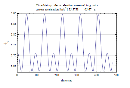
The following diagram gives the acceleration time history for the ride. This plot was
generated for the first 5 seconds of the ride in steady state. It shows that the maximum
acceleration did not exceed  during the simulation which included more than 5 complete
cycles.
during the simulation which included more than 5 complete
cycles.
The following table shows the ride configuration used to achieve the above time history. These values are the anticipated design parameters to use to complete the structural analysis, but these could change based on results of the structural design.
Length of beam  |
 meter meter |
Height of person head above beam  |
 meter meter |
Angular velocity of ride cabinet  |  Hz Hz |
Angular velocity of main vertical support column  |
 Hz Hz |
The preliminary design for this two-passenger ride features two components of non-collinear
angular velocity, and the head of each passenger experiences a maximum of  of
acceleration.
of
acceleration.
The design and calculations indicate that this will be a fun and light ride. Safety considerations were highlighted, and a management plan and team qualifications underscore the team's commitment to excellence and sound engineering. A more detailed stress analysis of the system will be delivered in December.
The rotating coordinates system has its origin as shown in the above diagram. The
coordinates system is attached to the column and therefore rotates with the column. The
following calculation determines the absolute velocity of the ride object head, shown above as
the circle  at distance
  from the center of beam. All calculations are expressed using
unit vectors of the rotating coordinates system and will be valid for all time. In
the rotating coordinates system, the ride object appears as shown in the following
diagram
from the center of beam. All calculations are expressed using
unit vectors of the rotating coordinates system and will be valid for all time. In
the rotating coordinates system, the ride object appears as shown in the following
diagram
Using the above diagrams, the absolute velocity vector is found as follows

Hence
Now the absolute acceleration of the passengers is found

Hence, the absolute acceleration of the ride object head is

Simplifying gives
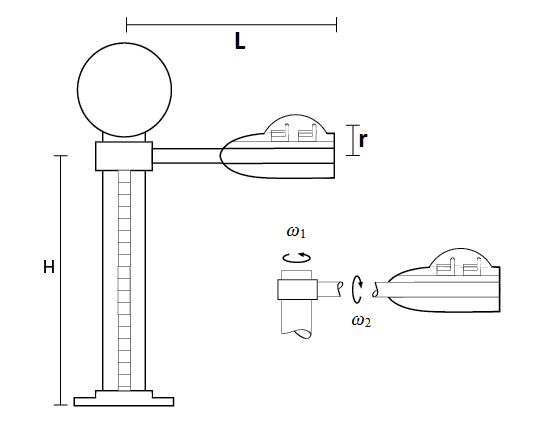
The following two diagrams illustrate the completed ride construction in place, showing the main dimensions and major components
Material parameters used are given in the following table
| Material used for beam | Aluminium |
 (Young's modulus) (Young's modulus) |
 GPa GPa |
| Shear modulus |  GPa GPa |
| Bulk modulus |  GPa GPa |
| Poisson ratio |  |
| Density |   |