 by converting the potential energy
stored in the device (as a result of raising a heavy mass
  to some height) into kinetic energy used to propel
the projectile mass.
The objective of this project is to design the most efficient Trebuchet by modifying 2 parameters in order to obtain the maximum projectile range.
Trebuchet is a mechanical device used to throw a projectile of mass  by converting the potential energy
stored in the device (as a result of raising a heavy mass
  to some height) into kinetic energy used to propel
the projectile mass.
The following diagram illustrates the model of the Trebuchet to use. This is the initial configuration.

The following are the system parameters
 density of beam per unit length
 center of mass of beam
 mass of projectile object.
 mass of the counter weight object.
 distance from pivot to center of counter object.
 distance from pivot to center of projectile object.
 distance of
  from pivot.
 total length of beam.
 initial angle from horizontal that
  is raised to.
 the height of the base support column.
 The following are the known input values:  ,
, 
Your goal is to select design values for  and
and  which will result in maximum horizontal range for the
projectile when it is ejected from its holding cup at the end of the beam.
Notice that as you change  , this will obviously change the center of mass of the beam and the
  as
well. This means that you need to remember to recalculate all the moments of inertias for
  and the
beam around the pivot each time you make design changes.
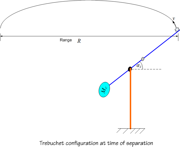
The projectile will be ejected when the reaction (the normal force) it makes with the beam becomes zero.
Hence your goal is to determine at what angle this will occur and the speed of the projectile at that instance.
This angle will be called the separation angle  . Once you obtain the speed of the projectile at ejection time,
you will be able to calculate the range of the projectile.
You allowed to vary the parameter  from
from  to
to  of the total length of the beam. For the initial angle
 you are allowed to vary this angle from
  up to
up to  .
.
All the energy is conserved. This means we can assume that all the potential energy is converted to kinetic energy. You can ignore friction, damping, and wind effect.
Assume the projectile has only normal reaction with the beam. Hence the projectile will be ejected from the holding cup when the normal force becomes zero between the projectile and the beam.
Derive the equations of motion and obtain an analytical expression for the separation speed of the projectile. Use this expression to obtain the horizontal range.
Obtain the optimum value for  which will result in a maximum horizontal range. This can be done by
writing a function which will calculate
  (the horizontal range) for different values of
  and by plotting
the result and seeing where the maximum is.
Plot the horizontal range as a function of  and
and  in a 3D plot showing where the maximum range
occurs.
Plot the horizontal range as a function of the separation angle  . The separation is the angle at which the
projectile will be ejected with speed
  as illustrated in the following diagram.
