Home
Run
Final
project report.
MAE 106. UCI. Winter 2005.
By Nasser Abbasi
March 22, 2005
Table
of contents
2 Block
diagrams of the controlled system
2.1 Pitcher controller
block diagram
2.2 Batter controller block
diagram
5.2.1 Batter
controller steps diagram
5.2.2 Batter
controller algorithm
6.1 Geometry and dimensions
of the playing field
6.2 Geometry and dimensions
of the batting mounting
8.1 Example output of one
test run
9.1 Batter controller
Matlab code
9.2 Pitcher controller
Matlab code
1 Overview
This is the report for the final project for MAE 106 course, UCI, winter 2005.
The project objective is to design a robotic system to play baseball for the final project for MAE 106. The project description and rules can be found at professor's Reinkensmeyer web site
http://www.eng.uci.edu/~dreinken/MAE106/mae106home.htm
Below is the general setup diagram taken from the project description document found in the above we site:
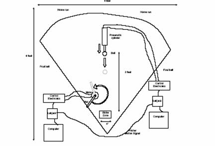
There are 2 main components to the project: the pitcher and the batter.
For both parts we used Labjack with Matlab to communicate between the PC and the mechanical components of the project (Piston and Motor). We used Matlab as the main tool to implement the control laws.
The basic design criteria we wanted to achieve are a fully automated and controlled batter with no manual nor visual control. This implied the restriction on the use of a manual controller to control the motor. We have started with the assumption that one is now allowed to use the keyboard once the game starts.
Due to this restriction we imposed on our design, the final solution consisted of software program where the controller was written in Matlab with heavy reliance on the LabJack Matlab interface calls. This solution produced some technical problems on its own, since this controller in essence in an open loop controller, we needed to have a good timing analysis done earlier and impede these timing estimates in the controller software. In addition, the sampling rate of Labjack was not fast enough to allow us to obtain more readings of the ball position as it is being hit by the piston; this resulted in less than optimal estimates being made on the position of the ball. Since it is not possible to track the position of the ball itself, implementing a feedback control system based on tracking the ball position is not possible (this would have been the optimal solution).
On the pitcher side, we controlled the speed of the piston by adjusting the voltage delivered to the piston actuator.
On the batter side (which was the more complicated controller), we detect when the ball was hit and at what speed, this in turn correlated to the amount of time delay before we issue the signal to start the motor to swing the bat. We also added logic to the bat controller to avoid attempting to hit balls with low enough speed which we calculated earlier (by running many tests) to be at such low speeds that the ball will most likely not be arriving in a straight line and hence will not hit the strike zone.
In addition, on the batter side, we added a mechanical stop mounted on the motor to be able to set the initial position of the bat to be at a fixed location before the start of each swing. This was critical to the mechanical design of our batter, since the bat controller is an open loop; hence having accurate timings is the most important aspect (by definition, an open loop contains no feedback and must rely on initial accurate timings). Hence, being able to set the bat at a fixed location before each swing allowed us to achieve this objective.
2 Block diagrams of the controlled system
2.1 Pitcher controller block diagram
The pitcher is an open loop proportional controller with a gain of one. The desired voltage is supplied, and the controller simply interfaces with Labjack to send this voltage to the piston (the plant). We add logic to the controller to add some delay and to move the piston back and forth before the voltage signal is send to the piston (the plant) to try to confuse the batter controller, but the final voltage send to the piston is the same as the desired voltage.
2.2 Batter controller block diagram
The batter is also an open loop proportional controller with a gain of one. The input to the batter controller is fixed at 5 volts (which is the maximum voltage labjack can send). This voltage moves the motor head at the maximum speed.
Initially we wanted the controller to control the speed of the motor. For fastballs, we wanted to speed up the motor, and for slow balls we wanted to slow down the motor.
However, after some testing, we discovered that the current amplifier we were given to use on this project was not designed for this purpose, it was only able to generate a constant current to run the motor at the same speed regardless of the voltage that was sent to it. (Actually the motor would run at a fixed low speed for voltages below 4 volts, and at fixed high speed for voltages over 4, but the point is that it was not possible to change the speed of the motor in direct proportion of the voltage being sent to the current amplifier we used)
For this reason, we designed the controller to delay more for slow balls and to delay less for fast ones, but to run the motor at the same speed for both cases. The block diagram for this open loop controller is shown below. In this diagram we show how the controller reads the piston head position signal from the piston in order to decide when to issue the command to the motor to start.
3 Circuit diagrams
The following diagram shows the full hardware configuration used with all the connections needed at the batter side
The batter reads the piston position signal as it arrives at the AI0 port of labjack. The following diagram combines both the pitcher and the batter circuits to better illustrate how the connection is achieved.
4 Equations used
Since the controller we used is a proportional controller with fixed gain of one, the control law is obviously very simple. However, the complexity came about in determining the amount of delay and in the calculation of the ball speed and in forcing labjack to use a fixed sampling rate so that our calibration will remain valid across different play stations.
So in what follows we describe how we performed the calibration.
We used a linear relation between the speed of the ball when it was hit and the amount of delay required before we swing the bat. We performed many experiments, hitting the ball at different speeds and determined the amount of delay needed to obtain a good swing for this speed (Please see the testing section for additional data on this).
The result of this testing is a number of data points. We then did a linear straight-line fit of the data and obtained the equation of the line. This line equation was used by the controller to determine the time delay needed based on the ball speed.
The line equation
![]()
Used in the controller is
![]()
In the above we assumed that the ball speed does not change greatly from the time the controller detected that the ball was hit until the time the ball arrives to the strike zone. Since the distance between the pitcher and the batter is small (three feets), and the ball is fairly smooth, this assumption is reasonable. In addition, the actual speed calculation itself is not very accurate due to the low sampling rate used by Labjack, which did not allow us to obtain more accurate estimates of the ball speed.
The speed of the ball was calculated as follows. The batter controller monitors the position of the piston head continuously by reading the piston head position signal which can vary from 0 volts upto 10 volts. The ball is situated half way between a fully extended and fully contracted piston. Hence a voltage reading of around 5 volts will indicate that the piston has hit the ball. The batter controller keeps track of the last 2 positions read from the piston and the amount of time elapsed between these 2 readings.
When it detects that the piston position has passed the half way mark, indicating that the ball was hit, it will calculate the speed using the equation
![]()
This value is then substituted in the delay equation discussed above to give the amount of delay in seconds needed before starting the motor.
In addition to the above, the batter controller will check if the speed of the ball is below a certain threshold. If so, the batter will not turn the motor in this case. The reason for this is that we found by experimentations that a slow ball will most likely not remain in a straight line and will not arrive to the strike zone. Hence we did not want to take the chance on trying to hit a ball that is going out anyway and losing a point. This will maximize our chances of winning. This threshold is currently set at 52 m/s.
5 Methodology used
We will consider the pitcher side and the batter side separately.
5.1 Pitcher controller logic
The logic of the pitcher controller is simple. We apply voltage, which causes the piston head to move. A voltage over 2.5 will move the head forward, and voltage below 2.5 will move the head backwards. We varied the speed we hit the ball at, and also moved the piston back and forth before hitting the ball in order to try to confuse the batter controller.
5.2 Batter controller logic
We have build 2 mountings on top of the motor mounting. One mounting to attach the bat, and another to attach a mechanical stop.
Controller starts by swinging the bat handle to the initial position, this will cause the bat handle to hit the mechanical stop mounting attached to the motor mounting. Immediately, the motor will stall, drawing current but not moving.
The controller will next turn the voltage off the motor and waits for the ball to be hit by the pitcher. The Batter controller continuously monitors the ball position signal coming from the pitcher.
The batter controller monitors the position of the piston head and calculates its speed after each sample reading using Labjack Matlab function calls.
When the batter controller detects that the position of the piston head has hit the ball (recall that the ball is located at a fixed position), then the speed of the ball will be known at that moment. It will be the speed of the piston head.
From the speed of the ball, the batter controller decides when to start the bat swing. The controller will always swing the bat at the maximum (5 volts) level motor speed.
The controller knows when to start the swing by a calibration process that we have performed prior to the start of the tournament. During calibration we did a number of runs and derived a line equation that allowed the controller to determine the delay needed given the speed of the ball.
Since the batter always starts from the same position (due to the use of the mechanical stop), this process resulted in a reasonable accurate swings designed to hit the ball at 90 degrees to the direction of the ball to obtain the maximum force on the ball.
At the end of each swing the bat handle will hit the mechanical stop on the other side, causing the motor to stall again. Controller will switch the voltage sign again, causing the bat to quickly swing back, hitting the mechanical stop again from the other side, and resting there until the next pitch.
This process will continue automatically. To help illustrate this process, the following diagram shows the main steps for the batter controller.
5.2.1 Batter controller steps diagram
5.2.2 Batter controller algorithm
We have used Matlab to implement the batter controller logic. The following is the algorithm for this controller.
reverse motor
voltage to swing clockwise to hit the mechanical stop.
start reading the
piston signal -- use LABKACK Matlab call.
Calculate the position and speed of the
piston head.
WHILE piston has not hit the ball
read next sample
from the piston signal
update
position and speed of the piston.
END WHILE
determine delay
needed based on ball speed. (use linear fitting)
pause the delay
needed.
issue a control
signal to the motor to swing at maximum speed.
delay for known
amount of time (calibrated) to allow bat to swing
fully.
END
6 Mechanical design features
6.1 Geometry and dimensions of the playing field
To be able to build the mounting for the bat handle and the bat itself, we needed exact dimensions of the playing field.
6.2 Geometry and dimensions of the batting mounting
The dimensions of the batting and mechanical stop mounting are shown below. We initially designed the mounting to allow us to add a potentiometer if we had to.
7 Parts list
- Series SRX stainless Steel body air cylinders with position feedback.
- Motor mounting (The size and dimensions are provided to us by the instructor).
- Mechanical stop mounting L-shaped.
- One mechanical bat arm to hit the ball with.
- 2 LU12 labjack’s with USB connection.
- 2 PC’s running windows and Matlab
- One current amplifier.
- A number of wires to connect current amplifier to motor and to labjack
- 2 screws and bolts to attach the motor mounting to the table.
- Power supply for the current amplifier (we used +12V DC provided by the training kit).
8 Testing with graphs
Since we implemented an open loop controller for the batter, most of the testing concentrated on calibration of the bat controller. We needed to able to estimate the amount of delay before a swing based on the speed of the ball. To accomplish this, as we discussed above in the methodology section, we ran many tests and collected many data points. This is a partial listing of data collected for calibration.
|
Voltage to piston (Volts) |
Calculated speed of ball (speed units) |
Amount of delay needed (milliseconds) |
|
4 |
51.04 |
79 |
|
|
49.97 |
81 |
|
|
55.60 |
75 |
|
|
61.52 |
69 |
|
|
56.07 |
74 |
|
|
|
|
|
3.9 |
50.26 |
80 |
|
|
52.03 |
78 |
|
|
49.25 |
81 |
|
|
52.92 |
78 |
|
|
52.76 |
82 |
|
|
|
|
|
3.8 |
53.08 |
83 |
|
|
47.52 |
84 |
|
|
56.00 |
83 |
For each piston voltage, the average of the speed was taken
and the average of the amount of the delay needed was also taken. This resulted
in a number of ![]() data points that we
fitted a straight line through to obtain the line equation.
data points that we
fitted a straight line through to obtain the line equation.
We also needed to fix the sampling rate of Labjack, and for this purpose we used one Labjack Matlab call that allowed us to specify the sampling rate to be used. Instead of using the standard call EAnalogIn() to read the piston position signal from AI0, we used the call AIBurst that also can read AI0, but in addition allowed us to specify a scan rate from 400 up to 8192 hz. We used 8192 Hz to be able to avoid the possibility of having one labjack running at different sampling rates at different play stations.
8.1 Example output of one test run
When the bat controller runs, it continuously displays basic results showing the speed of the ball being hit and the amount of delay. It will also show if the ball we is too slow, which in this case the batter will not attempt to hit. These messages made it easier to debug and calibrate the program. Below is such example output
>>
nma_motor
detected ball was hit.....
elapsedTime=62.000000 ms
last position=2.153320, currentPosition=5.410156
speed=52.529612
delay=0.517352
**************************************
detected ball was hit.....
elapsedTime=63.000000 ms
last position=2.211914, currentPosition=5.048828
speed=45.030382
delay=0.554848
ball too slow, will not try to hit...
**************************************
detected ball was hit.....
elapsedTime=64.000000 ms
last position=2.192383, currentPosition=5.668945
speed=54.321289
delay=0.508394
**************************************
detected ball was hit.....
elapsedTime=67.000000 ms
last position=4.619141, currentPosition=8.447266
speed=57.136194
delay=0.494319
**************************************
9 Appendix
In the appendix we show the Matlab code used for the bat and pitcher controller.
9.1 Batter controller Matlab code
For the batter it was not clear if the rules of the game allow one to touch the keyboard once the game starts.
For this reason, we have 2 versions of the bat program. One is called nma_motor_auto.m, and the other is called nma_motor_manual.m.
The first program above is the one discussed in details in this report, since it is the fully automated version and requires no manual intervension once it starts. The second version is a modified version that requires the user to hit the keyboard to start the motor running resulting is the bat moving.
Below is the code for both version of the controller.
9.1.1 nma_motor_auto.m
%
% MAE Final project.
UCI, winter 2005
% motor controller script.
% by Nasser Abbasi
%
% This script implements
the open loop bat controller
% See the project report for background information
% about this project.
%
% define some constants used in the program
LEFT=5;
RIGHT=0;
HIGH_V=5;
LOW_V=0;
DEBUG=1;
TRUE=1;
FALSE=0;
BALL_POSITION=5;
SAMPLE_RATE=8192; %Hz
LOW_SPEED_THRESHOLD=0;
SLOPE=(0.25-0.12)/(65.33-51);
pistonLastPosition=0; %set the piston last position to be fully
retracted
while
TRUE
EAnalogOut(0,0,HIGH_V,RIGHT); %set the handle
pause(0.1); %wait to reach mechanical
stop.
EAnalogOut(0,0,LOW_V,RIGHT); %turn off motor
BallHit=FALSE;
[count tnow err id]=ECount(0,0,0);
while ~BallHit
% replace the call below by AIBurst.
To allow better control
% on the sampling rate.
% [currentPosition o err id]=EAnalogIn(0,0,0,0);
tlast=tnow;
[pistonCurrentPosition s scans over err
id]=…
AIBurst(0,0,0,0,0,1,0,0,SAMPLE_RATE,0,0,0,1,1,0);
if err~=0
fprintf('Failed
AIBusrt call. error is %s\n',GetErrorString(err));
return;
end
[count tnow err id]=ECount(0,0,0);
%if
DEBUG fprintf('currentPosition=%f\n',currentPosition); end;
%if
DEBUG fprintf('tnow=%f, tlast=%f\n',tnow,tlast); end;
% if(DEBUG)
% if(currentPosition>2) fprintf('currentPosition=%f\n',currentPosition);
end
% end
if(pistonCurrentPosition>BALL_POSITION)
if pistonLastPosition<=BALL_POSITION
if DEBUG fprintf('detected
ball was hit by piston.....\n'); end;
elapsedTime=tnow-tlast;
fprintf('elapsedTime=%f ms\n',elapsedTime);
speed=(pistonCurrentPosition-pistonLastPosition)*1000/elapsedTime;
if DEBUG fprintf('ball
speed=%f\n',speed); end;
fprintf('piston last position=%f, piston currentPosition=%f\n',...
pistonLastPosition,pistonCurrentPosition);
if speed>LOW_SPEED_THRESHOLD
BallHit=TRUE;
else
fprintf('ball too slow, will not try to
hit...\n*********************\n');
end
end
end
pistonLastPosition=pistonCurrentPosition;
end %while waiting for ball to be hit
if(speed<51)
delay=0.25+SLOPE*(51-speed);
else
delay=0.25-SLOPE*(speed-51);
end
if DEBUG fprintf('motor delay=%f\n',delay); end;
pause(delay);
EAnalogOut(0,0,HIGH_V,LEFT); %HIT the ball.
pause(0.5); %wait for bat to reach mechanical stop.
EAnalogOut(0,0,LOW_V,LEFT);
%stop the motor
fprintf('**************************************\n');
end
9.1.2 nma_motor_manual.m
%
% MAE Final project.
UCI, winter 2005
% motor controller script.
% by Nasser Abbasi
%
% This script implements
the open loop bat controller
% for the manual version of the batter,
%
% See the project report for background information
% about this project.
%
% define some constants used in the program
LEFT=5;
RIGHT=0;
HIGH_V=5;
LOW_V=0;
DEBUG=1;
TRUE=1;
FALSE=0;
while
TRUE
EAnalogOut(0,0,HIGH_V,RIGHT); %set the handle
pause(0.1); %wait to reach mechanical
stop.
EAnalogOut(0,0,LOW_V,RIGHT); %turn off motor
fprintf('hit
any key to turn bat.....\n');
pause;
EAnalogOut(0,0,HIGH_V,LEFT); %HIT the ball.
pause(0.5); %wait for bat to reach mechanical stop
EAnalogOut(0,0,LOW_V,LEFT);
%stop the motor
End
9.2 Pitcher controller Matlab code
EAnalogOut(0,0,5,0);
EAnalogOut(0,0,0,0);
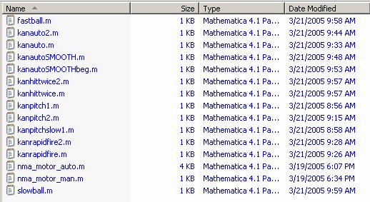
Attached floppy disk contains more examples of the pitcher code and the code for the batter. This is the content of the flopy disk attached showing all the matlab .m files used.