LAB #1 report. MAE 106. UCI. Winter 2005
Nasser Abbasi, LAB time: Tuesday 1/11/2005 11:00 AM-1:50 PM
Answer
1.
-
Oscilloscope: This is a device to allow one to analyze and display the
electric signal in the circuit. One can use it to display the electric signal
trace on the screen and to measure different properties about the signal. One
can use it to display different properties about the voltage, such as the
max/min, vpp. In addition it is used to measure the frequency properties of
the signal.
-
Function generator: This device is attached to the training kit, and was used
to generate electric signals of different time-domain shapes, such as square,
triangular and sinusoidal signals. One can also adjust the frequency,
amplitude and phase offset at which these signals are generated.
-
Solderless breadboard: This makes it convenient to quickly build and connect
simple circuits since it eliminates the need to make soldering to connect
different parts of the circuits together.
-
potentiometer: Also called 'pot'. This allows one to adjust the voltage
entering one branch of the circuit by allowing one to adjust the resistance by
turning a knob. It is a Voltage divider.
Answer 2.
The MOSFET has 3 ports.
 .
We control the voltage supplied to the gate
.
We control the voltage supplied to the gate
 by using a pot. When
 changes, this causes voltage at port
 to change
 as well. But voltage across the motor depends on
 hence we can control the voltage across the motor.
By controlling the voltage across the motor, we control the torque generated
by the motor.
Note that the change between
 and
and
 is not linear. As
 changes, the internal MOSFET resistance
 changes, and this causes
 to change.
The voltage across the motor depends on
 by the relation
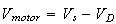 where
where
 is the fixed source voltage.
By using MOSFET only to control voltage to the motor, it acted as an
approximation to an on/off switch. This is because a small increment in
 caused a sudden large increase in
 to appear. However, as
 continued to increase,
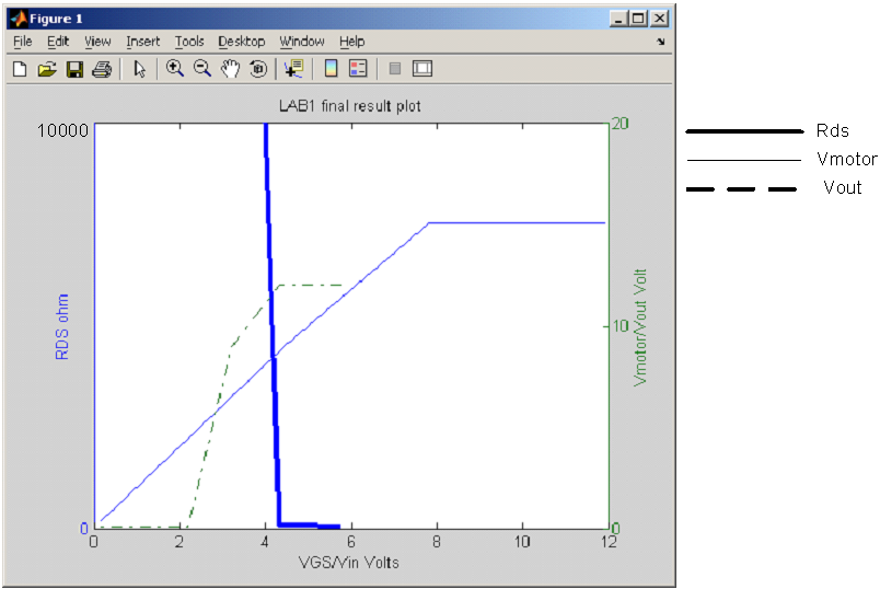
 did not continue to increase as well, but remained steady. See plot of
 vs.
vs.
 .
This shows that the nonlinearity of MOSFET makes it hard to use to control the
speed of the motor.
.
This shows that the nonlinearity of MOSFET makes it hard to use to control the
speed of the motor.
On the other hand, a small voltage at the gate caused a large voltage to
appear across the motor, so this shows that MOSFET acted as a device that can
be use to supply power to other devices.
Answer 3.
When we used just the MOSFET to control the speed of the motor, it was hard to
slow down or speed up the motor shaft spin. The motor will either spin or stop
by changing the pot dial across the range of the dial. This is due to the
nonlinearity of the MOSFET. So, to use MOSFET to supply power to the motor, we
need to be able to better control the voltage it generates, and to do this, we
use an Op-Amp.
By using an OpAmp, using negative feedback, we feed the voltage output from
MOSFET back into the opAmp. This causes Voltage at the gate
 to adjust so that voltage output from MOSFET follows voltage input to the
opAmp.
to adjust so that voltage output from MOSFET follows voltage input to the
opAmp.
So, by changing the input voltage to the OpAmp via the use of the pot, and
having negative feedback, the voltage output from MOSFET follows the input
voltage more closely. Since output voltage from MOSFET is linearly related to
the speed of the motor, we are now able to better control the speed of the
motor. This circuit is shown in figure 6 in LAB1 handout.
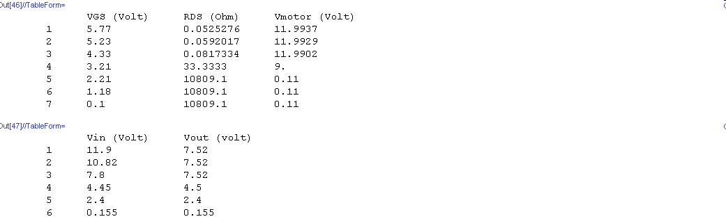
ANSWER 4
I have written a simple program to generate the diagrams required from the
data collected in the Lab. This is the final plot output. First, this is the
data collected: