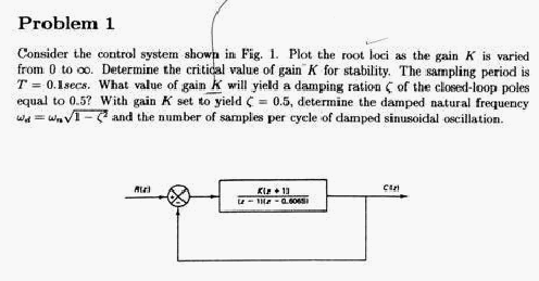
HW7, MAE 171. Spring 2005. UCI
Nasser Abbasi

step 1
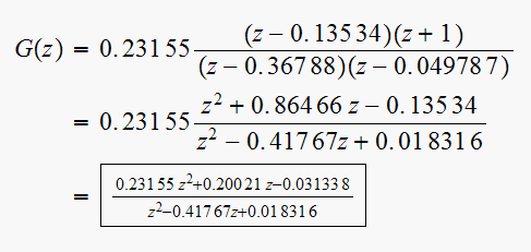
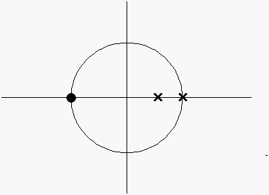
Identify the position of the open loop poles and zeros on the Z-plane. Since
the open loop tf is
 then
we have a zero at
 and a pole at

step 2
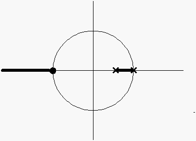
Identify R.L. on the real line.
Number of poles and zeros must be odd to the right of the line segment for that segment to be on the R.L., hence we see that the R.L. on the real line is as follows.
step 3
Find asymptotes.
Number of asymptotes is
 where
where
 is number of finite open loop poles, and
 is number of open loop finite zeros.
Hence
 ,
so there is one asymptote. The angle the asymptote makes with the real axis is
 for
for
 (this is for
 .
.
Since
 ,
then we count
 up to zero only
(
 ,
so we obtain angle as
 .
.
Now find where the center of the asymptote on the real line.
This is given by

step
4
Find break away and break in points on the real line. Note_1
The characteristic equation is
 hence
hence
 ,
then

Hence
 leads to
 ,
Solution is

 is between 2 poles, hence it is a breakaway point, and the solution
 is between 2 zeros (one zeros at
 )
hence that is a break-in point. So far we have this plot.

step 5
Find angle of departure of the break away point. (point
 ).
).
There are 4 branches at this point. Hence each branch makes
 with the other branch. Since one branch is fixed (from
 to
to
 ),
hence R.L. makes
 with the real line. Similarly for angle of arrival at point
 ).
Hence RL is a circle that has on its perimeter the point
 and the point
 )
(we are not asked to prove this). Since RL starts at a poles and ends at a
zero, then one branch will arrive at the break-in point and moves to the zero
located at
 and the other branch will move to the other zero locate at
 .
Hence RL looks as follows
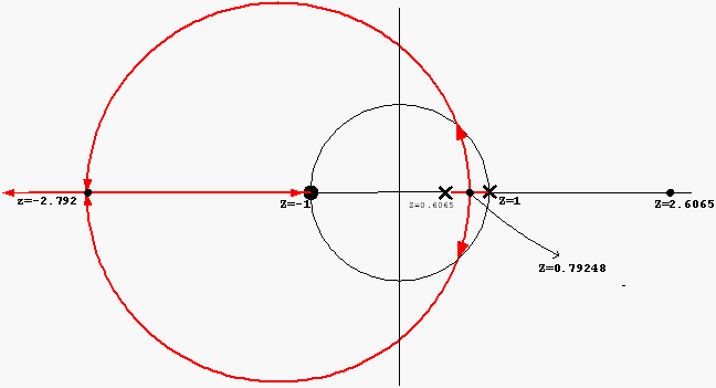
The center of the RL circle is located at midpoint between
 and
and
 i.e. at point

Now to determine the critical value of gain
 for
stability.
 will be zero at a pole and will be
 at a zero. When RL meets the unit circle the system will become unstable.
We can use Jury tests to find the range of stable K.
The characteristic equation is
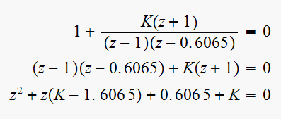
Hence we need
 or
or
 or
or

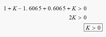
From requirement that
 we obtain
From requirement that
 we obtain

Which does not provide any new range information for
 as
as
 cancels out.
Since this is a second order system, no need to construct Jury table. We can
stop here. Hence the range of
 for stability is

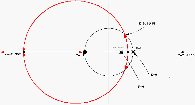
We can now find where the R.L. cross the unit circle.
Since
 ,
when
 we get
 Solution
is
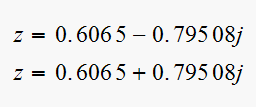
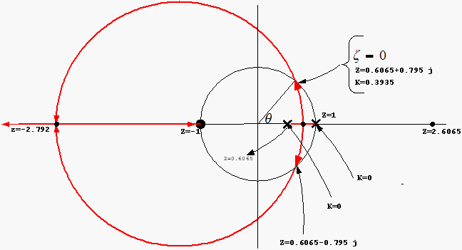
Hence

But
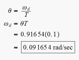
This is
 when the system becomes unstable, ie. at
 and
and

 ,
what value of gain
 will
yield
 is a function of the position of the closed loop discrete system as expressed
by the relation
 .
The position of the closed loop poles is a function of
 (since by definition the closed loop poles move on RL as
 changes).
The characteristic equation is
 ,
then the closed loop poles are the roots of this equation. which are

Taking one of the roots, we obtain

Note that
 at
at
 and
and
 will
increase as
 becomes smaller.
By trial and error decrease
 and for each
 solve for
 in the above equation. Once
 is found,
 are known. Find
 and check if the desired value. Continue this process until we reach the
required
 value.
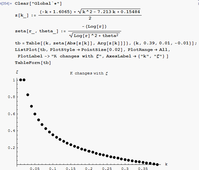
This is a simple script which solves this. The answer is

A table is generated showing how
 changes with
 ,
this is a partial listing showing when

k Damping Ratio
0.066, 0.4927400303245694
0.065, 0.49825440726325265
0.064, 0.5038857217422561
0.063, 0.5096384660975533
This below is the script with a plot showing how
 changes with

With the gain
 set
to yield
 ,
determine damped natural frequency and the number of samples per cycle of
damped sinusoidal oscillation
Since
 fixes the position of the closed loop pole on the R.L., then we can now find
the angle
 that the pole makes with the real axis in the Z plane.
For
 ,
substitute into equation (1) above, we obtain the pole
location.
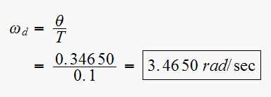
 Hence
Hence

Now we can find

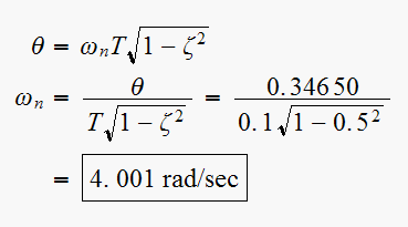
We can also
find (but problem did not ask for
it).
Now we find

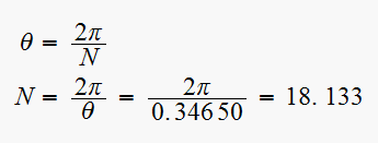
Since
 must be an integer (it is the number of samples per cycle) then we must
choose
 or
or
 .
Which one to choose?
If we choose the lower value, i.e.
 ,
this means we choose a larger
 ,
i.e. larger gain
 or
smaller
 ,
and the reverse will happen if we select
 ,
the pole will be further away from the critical
 since
since
 will be smaller. It is better I think to select the larger value
 to improve the relative stability by staying away from the edge if the unit
circle. So I select

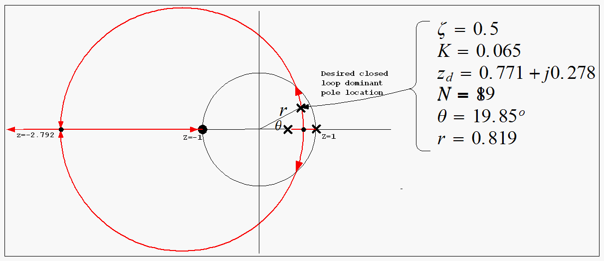

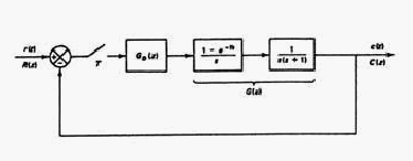
 the
damping ratio of the dominant closed loop poles is

 the number of samples per second is 8
 ,
the sampling period is

First, assume there is no compensator
 .
.

Note that the uncompensated open loop poles are at


The uncompensated system characteristic equation is
 hence the characteristic polynomial is
 or
or

Hence uncompensated closed loop poles (roots of this polynomial) are at

therefor


It is clear that we need a compensator, since we want
 to be
to be
 which is not the case as is.
Now find the desired closed loop location to meet the specifications.
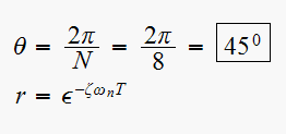
but

Then from (1) we find


Hence desired closed loop dominant pole must be located
at and at
 Hence desired closed loop pole location
is
Now that we know where the desired closed loop pole must be located, we can add a compensator such that the angle condition is satisfied for this desired pole.
This drawing shows the uncompensated
 poles/zeros and the desired closed loop location.
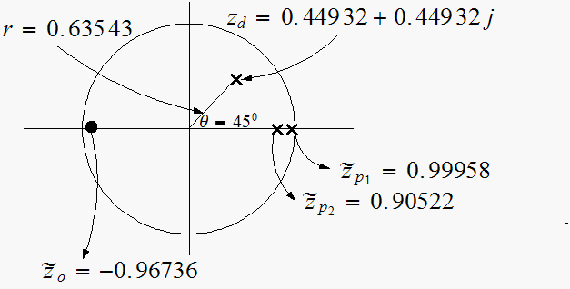
Now we add the lead compensator such that with its pole and zero we will
satisfy the angle condition at
 .
Since this is a lead compensator, then its zero will be to the right of its
pole.
First let find out the angle deficit before adding the compensator.
With simple geometry we can find the sum of uncompensated angles
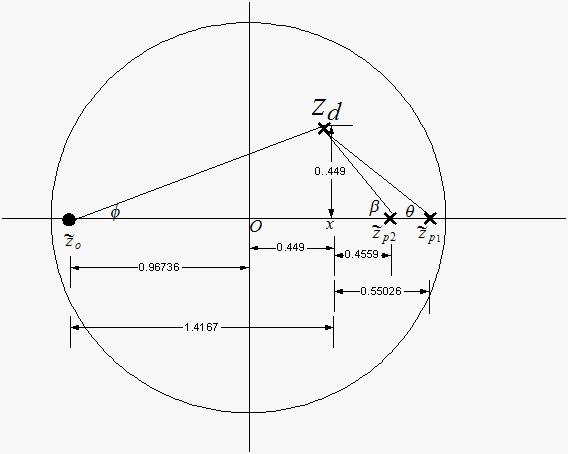
 ,
hence pole
 makes
makes
 with desired closed loop pole.
 ,
hence pole
 makes
makes
 with desired closed loop pole.
 ,hence zero
 makes
makes
 with desired closed loop pole.
Hence

Since the angle condition requires that the sum of angles with the desired
closed loop pole be

 we need to locate the compensator pole and zero to meet this condition.
Put the compensator zero
 on top of the uncompensated open loop pole
 ,
and the compensator pole on the real axis such that the angle condition is
met. Hence now we have this diagram
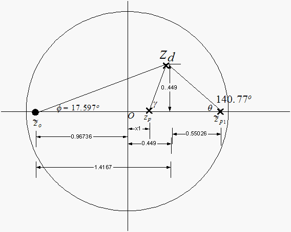
The angle
 did not change, hence we can now find angle


Hence

Therefor we can find the lead compensator pole location
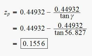

Therefor the lead compensator now is

Now we need to find
 Use magnitude condition on the characteristic equation for the compensated
closed loop system.

Where

Note that when finding the magnitude values we do not consider the canceled poles/zeros). We get

But

Hence

Hence

Hence lead compensator transfer function now
is
So the compensated open loop T.F. now is

To verify and to check internal consistency of the computation, find the
closed loop pole of the compensated system and verify it is the same as the
one we started with. The characteristic polynomial of the compensated system
is Hence
the close loop poles of the compensated system are the roots of the above
polynomial. Solution is:
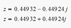 which
matches the desired closed loop pole we started with. (see equation (2)
above).
This completes the design the lead compensator.

From the open loop for the compensated system, equation (3) above

The pole at
 can be approximated to be at
 ,
so I can write

This is a
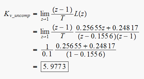
Hence


 by
a factor of 2
We want
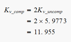
Hence now


The lag compensator is
 ,
let
,
let
 per problem specification. Hence the new open loop now is
 ,
hence we want
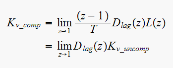
But
 ,
hence
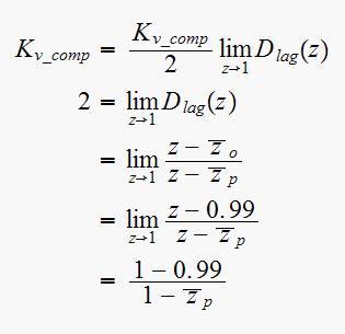
Hence
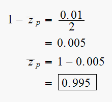
Hence the lag compensator is


Therefor the final compensated open loop now is

To verify that the closed loop pole still remain at the desired location, the
characteristic polynomial is

Solution is
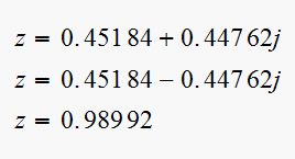
So the desired dominant poles remain close to the same location. Compare with equation (2). Not exactly the same location (see equation 2), but very close.
Error in
 ,
the length of desired pole is

and error in
 ,
phase of desired pole

So shift in position is less than one tenth of a percent.
System should be tested now to verify this slight movement of the closed loop pole does not have adverse effect.
This diagram shows the final poles and zeros of the final compensated system.
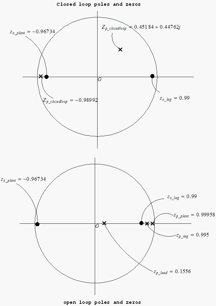
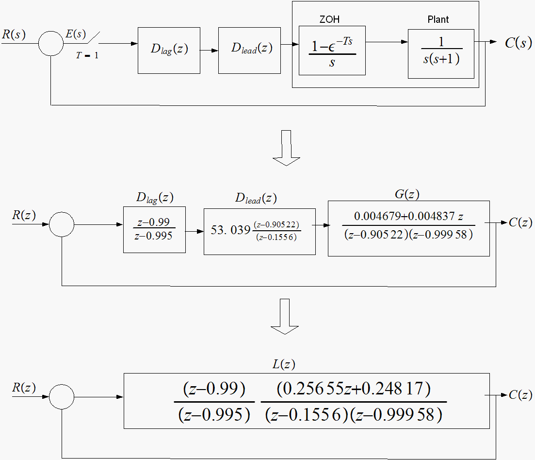
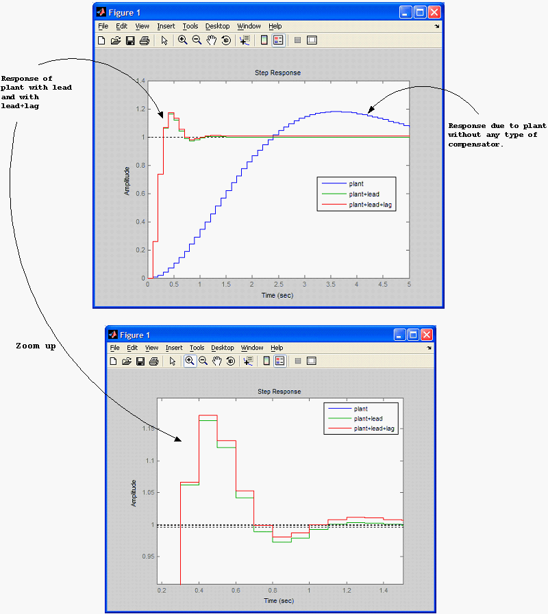
The step response for the plant only, and the plant+lead and plant+lead+lag is shown below to see the effect of adding the compensators.
The step response of the plant only shows that the response takes longer to
reach the desired value, the settling time is longer, as well as the rise
time. But adding the compensator does not seem to have an effect of the
maximum overshoot
 .
.
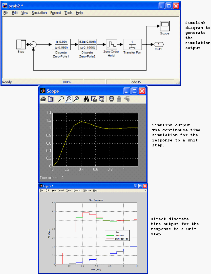
When the lead and lag compensators are added, the response reaches the desired value much faster. The rise time is about 1/2 second compared with about 3.5 seconds with the plant alone. The settling time when compensators are present is about 1 second, while without compensators the settling time is about 6-7 seconds.
When comparing the plant+lead vs plant+lead+lag on the step response, the presence of the lag compensator does not seem to have much of an effect, actually looking at the zoomed area, when using only the lead compensator, the step response is a little better without the presence of the lag compensator.
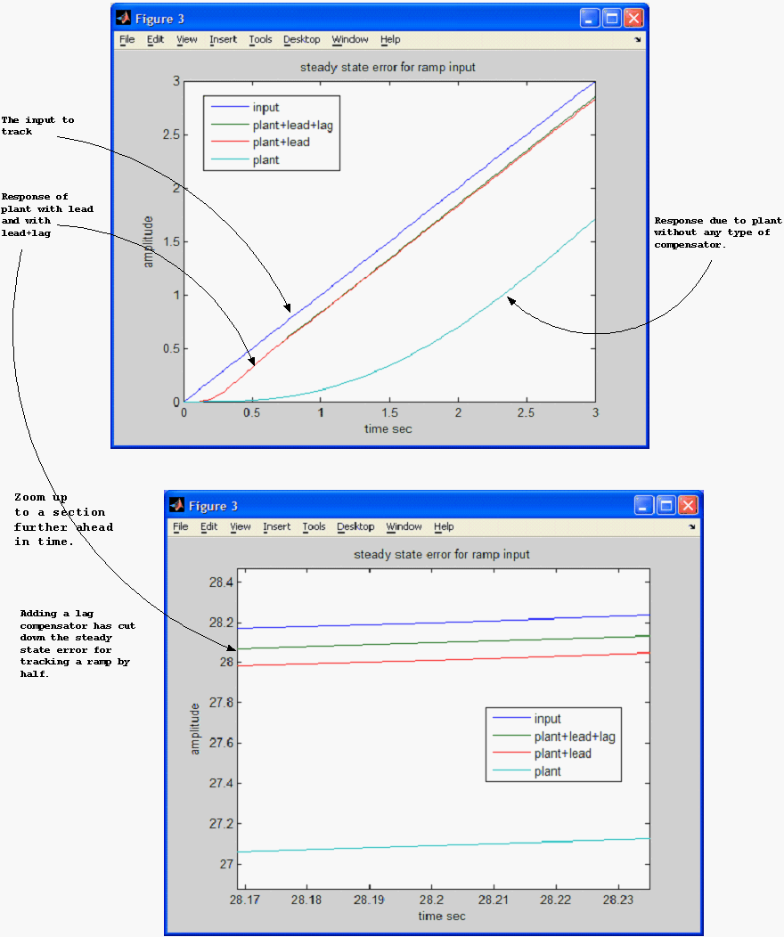
The effect of the lag compensator is more evident when looking at the steady state error for a ramp response. In that instance, the presence of the lag compensator has improved the steady state error by making it smaller than when using a lead compensator only. Actually the steady state error for tracking a ramp input is half that when using a lead compensator only.
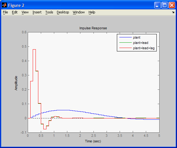
The diagram below shows the impulse response for the plant alone, then plant+lead, then plant+lead+lag for comparison.
Using simulink we can obtain the continuous time system response to a step input. This is the result.
Given
 and
and
 ,
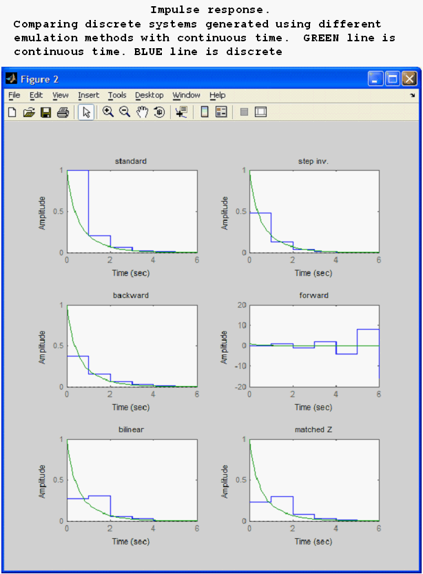
find equivalent discrete-time systems using
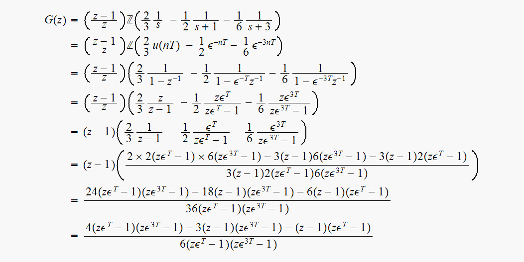
standard Z transform (impulse invariance)
step invariance
backward difference
forward difference
bilinear z-transform
matched z-transform
This tables summarizes the results
| Standard Z transform |  |
| step invariance |  |
| backward difference |  |
| forward difference |  |
| bilinear z-transform |  |
| matched z-transform |  |
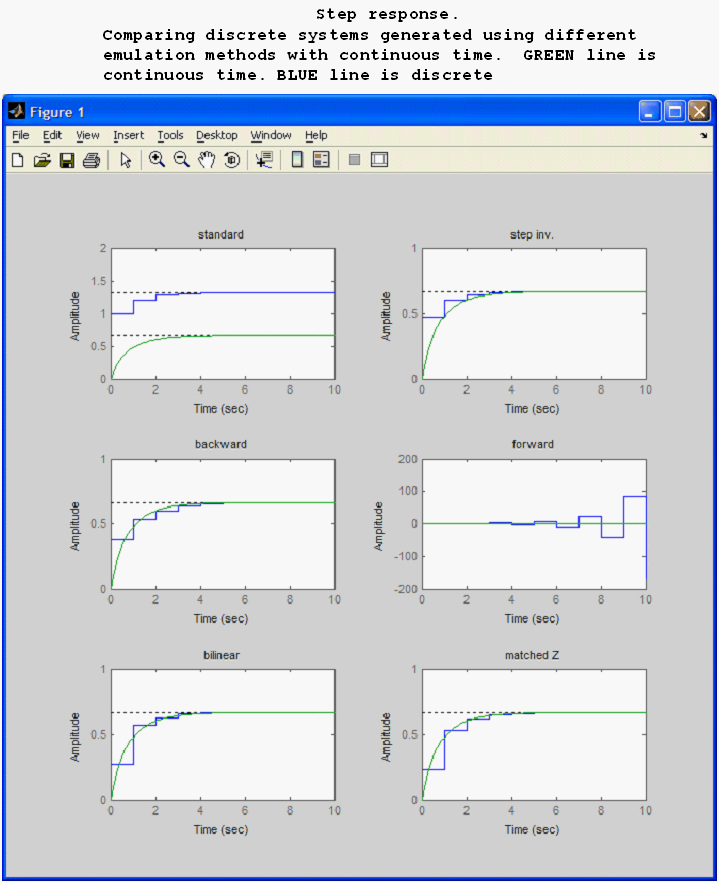
To help understand more the emulation methods, a step response using each different emulation method is shown alongside the Laplace transform response.


Hence


For
 we get


Hence
Since
 we get

use

Hence
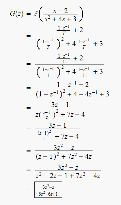
use

Hence
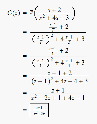
use

since
 ,
we get

Hence
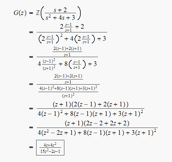

 has one finite zero at
 ,
one zero at
 and 2 poles at

Hence

for
 we obtain

Now to find

Since continuous system is type
 ,
then use position error constant

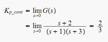
for the discrete system

Hence

Hence
